We pursue the best system through strict design criteria, quality management, and reliable structural strength analysis.
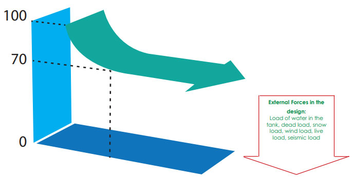
The basic of structure analysis is designed by safety factors against threshold values. We know-how lies in the optimal safety factor in consideration of external force in the design that is expected base on physical properties after long-term use of SMC material.
In designing, the tanks ignores initial value(100%) of the physical properties of SMC material
and considers the safety factor to a minimum value(70%). Therefore, our water tank
guarantees long-term endurance.
| Items | Design Conditions |
|---|---|
| Earthquake | Lateral Seismic Coefficient KH=1/3G |
| intensity of illumination | less than 0.1% |
| Design Conditions | Hydrostatic Pressure | |||||||||||||||||||||||||||||||||||||||||||||||||||||||||||||||||||||
|---|---|---|---|---|---|---|---|---|---|---|---|---|---|---|---|---|---|---|---|---|---|---|---|---|---|---|---|---|---|---|---|---|---|---|---|---|---|---|---|---|---|---|---|---|---|---|---|---|---|---|---|---|---|---|---|---|---|---|---|---|---|---|---|---|---|---|---|---|---|---|
| Wind Velocity: 60m/sec. 134 mph Snow load: 60kgf/m2 or 12.3 lb/ft2 Man load: 120kgf or 265 lb Seismic load: Horizontal SeismicCoefficient: Kh=0.3 Water temperature 60˚C (max) or 104˚F, this could be increased to 80˚C or 176˚F with special sealant. Anchor bolts shall be used to tie down a tank at the designed points. Note: 1. Panel strength is the actual bursting’ pressure 2. Design can also be made for Kh 2/3, 1.0 and 1.5 |
|
|||||||||||||||||||||||||||||||||||||||||||||||||||||||||||||||||||||
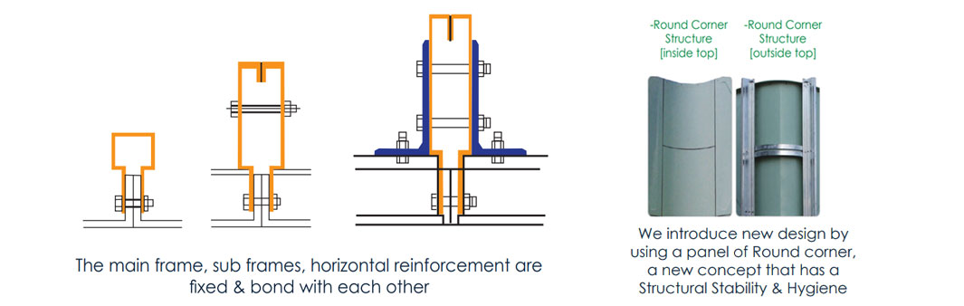
Internal Reinforcement System
 The excellent strength, durability and water tightness of the MULTANK are obtained
by connecting inner panels with stainless steel braces & tie-rods are installed inside
of the tank to improve the strength and stability of the tank structure. Corrosionproof
PE heat treated stainless steel tie-rods and GRP tie - rods are applied.
The excellent strength, durability and water tightness of the MULTANK are obtained
by connecting inner panels with stainless steel braces & tie-rods are installed inside
of the tank to improve the strength and stability of the tank structure. Corrosionproof
PE heat treated stainless steel tie-rods and GRP tie - rods are applied.
| 1 | Base Bracket |
| 2 | Anchor Bracket |
| 3 | Base Frame |
| 4 | Air Vent |
| 5 | Corner Frame |
| 6 | Corner Bracket |
| 7 | Cross Plate |
| 8 | Flange Bar |
| 9 | Tie Rod |
| 10 | Roof Stay |
| 11 | Roof Stay Fixer |
| 12 | Ladder |
| 13 | liner |
| 14 | Water Level Guage |
Internal Stay Configuration
1. Materials
2. Inner stay configuration
Minimize the transformation of the side(transformation of 1% or less of the tank height), and it should be so designed as to improve the safety and life of tanks.
| Items | Materials | Specification | Design According |
|---|---|---|---|
| Inner Stay | STS 306 + P.E Coating | Round Bar Ø10.6 (M12 Screw Processing) | BS5950 |
| Internal Bracket | STS 316 Over | 170 X 60 X 5T Over | BS5950 |

External Reinforcement System
 MULTANK exterior reinforcement system refers to a system that has been
designed to withstand stress that occurs due to the hydraulic pressure
exerted on the outer part of the tank.
MULTANK exterior reinforcement system refers to a system that has been
designed to withstand stress that occurs due to the hydraulic pressure
exerted on the outer part of the tank.
| 1 | Air Vent |
| 2 | Corner Frame |
| 3 | External Flange Bar |
| 4 | External Bracket |
| 5 | External Ladder |
| 6 | External Frame |
| 7 | Partition Frame |
| 8 | Partition Frame Fixer |
| 9 | Lower Frame Fixer |
| 10 | Roof Stay |
| 11 | Roof Stay Fixer |
| 12 | Partition Frame Fixer |
| 13 | Lower Frame Fixer |
| 14 | Water Level Guage |
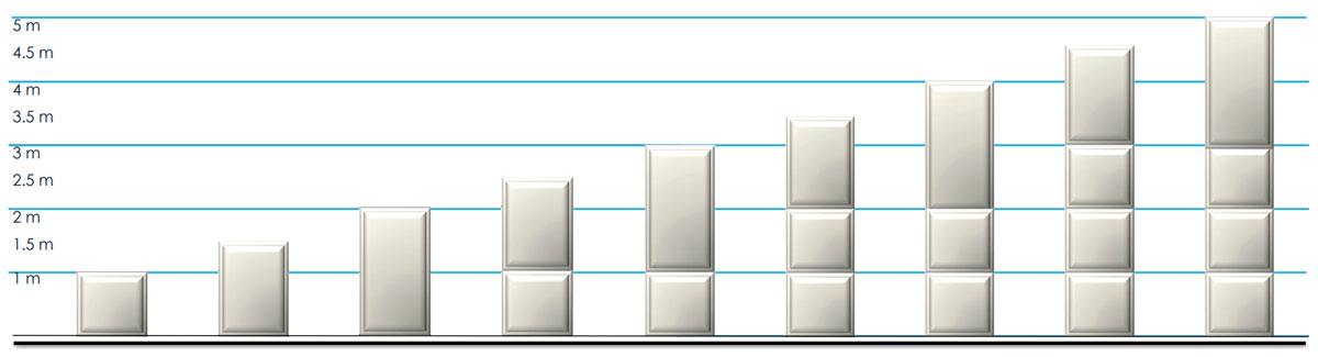
Panel Composition by Height